General view
🔥 This feature is currently considered experimental. Try it out and give feedback by reporting bugs and suggesting new features. It’s not recommended for production use.
👥 This feature is available to all users.
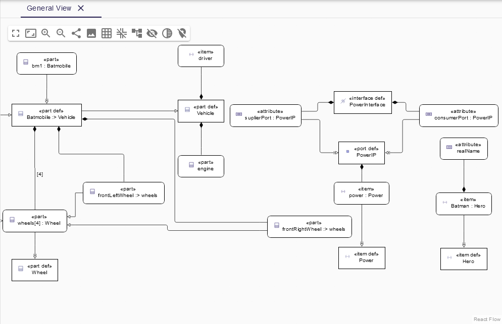
The General view is employed to display any members of exposed model elements. It is the most general view, enabling the presentation of any model element.
|
This view in SysON is implemented as an unsynchronized diagram. This means that users need to manually add existing elements to the diagram to visualize them. It doesn’t display all the information stored in the model by default. It relies on the exposed elements of the ViewUsages, on which the diagrams are created. |
1. Create New General View Diagram
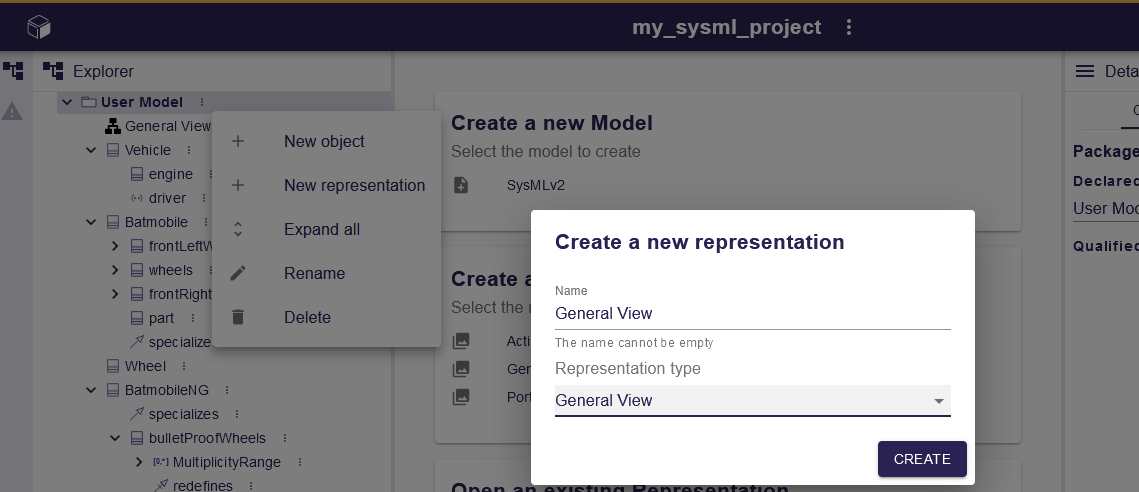
Users can create a General view diagram on any element that inherits from the Namespace type.
2. Toolbar
The Diagram panel has global actions grouped in a horizontal toolbar underneath the diagram tabs.

This toolbar has the following actions:
-
Display full screen,
-
Fit selection to screen,
-
Zoom group: Zoom In, Zoom Out,
-
Share the diagram link,
-
Export diagram as SVG,
-
Toggle snap to grid,
-
Show helper line to align elements,
-
Arrange all elements,
-
Reveal hidden elements,
-
Reveal faded elements,
-
Unpin all elements,
-
Select element in the diagram,
-
from what is selected in the Project Explorer.
-
-
Filter elements
-
this menu allows to select elements represented in the diagram, and then apply an action on them (collapse, expand, show, hide, fade, reveal faded, pin, unpin).
-
-
SysML actions
-
show/hide icons on diagram elements,
-
show/hide inherited members,
-
show/hide inherited members from standard libraries.
-
3. Element representation
Six categories of elements can be represented in a General view diagram.
3.1. Definition elements
The following Definition elements can be displayed in the General view diagram:
-
Action Definition,
-
Allocation Definition,
-
Attribute Definition,
-
Constraint Definition,
-
Enumeration Definition,
-
Interface Definition,
-
Item Definition,
-
Metadata Definition,
-
Occurrence Definition,
-
Part Definition,
-
Port Definition,
-
Requirement Definition,
-
UseCase Definition.
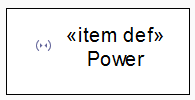
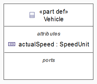
Definition elements are represented by a rectangular node style. The keyword with the "Def" specification is defined in the node label.
3.2. Usage elements
The following Usage elements can be displayed in the General view diagram:
-
Accept Action usage,
-
Action Usage,
-
Allocation Usage,
-
Attribute Usage,
-
Constraint Usage,
-
Interface Usage,
-
Item Usage,
-
Occurrence Usage,
-
Part Usage,
-
Port Usage,
-
Requirement Usage,
-
UseCase Usage.
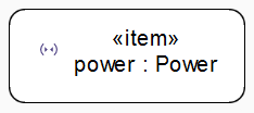
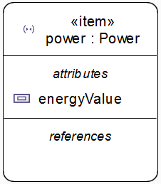
Usage elements are represented by a rectangular node style with rounded corners.
3.3. Elements in Definition elements
The following elements in Definition compartments can be displayed in the General view diagram:
-
Action Definition can contain in its body Action, Accept action, Start action, Done action, Fork action, Join action, Merge action, Decision action and Perform action,
-
Attribute in Attribute Definition/Interface Definition/Item Definition/Metadata Definition/Occurrence Definition/Part Definition/Port Definition/Requirement Definition,
-
Constraint in Constraint Definition,
-
Documentation in all Definition elements,
-
Enumerated Value in Enumeration Definition,
-
Interface in Interface Definition,
-
Port in Interface Definition/Part Definition,
-
Reference in Metadata Definition/Port Definition,
-
Occurrence in Occurrence Definition,
-
Assumed Constraint in Requirement Definition,
-
Required Constraint in Requirement Definition.
Each element in a Definition node is represented in a dedicated compartment. A Definition node can have several compartments if the Definition element can contain multiple kinds of elements. Each compartment is distinguished by a specific identifier.
3.4. Elements in Usage elements
The following elements in Usage compartments can be displayed in the General view diagram:
-
Action Usage can contain in its body Action, Accept action, Start action, Done action, Fork action, Join action, Merge action, Decision action and Perform action,
-
Item in Action Usage,
-
Allocation in Allocation Usage,
-
Attribute in Attribute Usage/Interface Usage/Item Usage/Part Usage/Port Usage/Requirement Usage,
-
Reference in Attribute Usage/Item Usage/Port Usage,
-
Constraint in Constraint Usage,
-
Documentation in all Usage elements,
-
Port in Interface Usage/Part Usage,
-
Occurrence in Occurrence Usage,
-
Assumed Constraint in Requirement Usage,
-
Required constraint in Requirement Usage.
Each element in a Usage node is represented in a dedicated compartment. A Usage node can have several compartments if the Usage element can contain multiple kinds of elements. Each compartment is distinguished by a specific identifier.
3.5. Package element
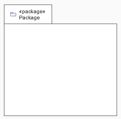
Package elements can be represented in a General view diagram.
It is represented by a folder and its label has the keyword package.
3.6. Annotating element
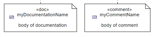
Annotating elements, such as Documentation and Comment elements, can be represented in a General view diagram.
It is represented by a note node and its label contains the body of the Annotating element in addition to its declared name.
The label of Documentation node also includes the keyword doc whereas the label of Comment node includes the keyword comment.
3.7. Relationships
The following relationships can be displayed in the General view diagram:
-
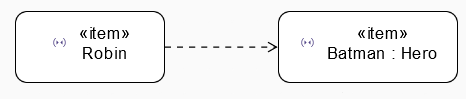
Dependency,
-
Subclassification,

-
Redefinition,

-
Subsetting,

-
Feature Typing,

-
Allocation,

-
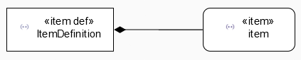
Containment relation,
-
Succession,

-
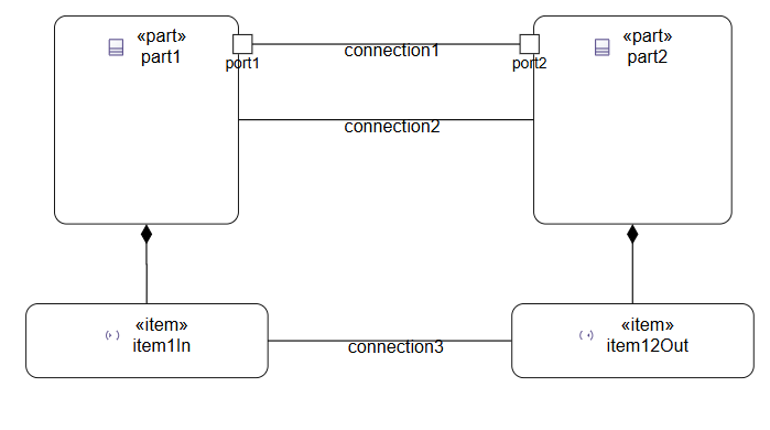
Connection Usage.
4. Manage elements
4.1. Create element
Users can create elements from the diagram background by right-clicking to display the palette. In this palette, element creation tool are grouped by type in tool sections according to their type. Users can click a tool section and then select the desired creation tool.
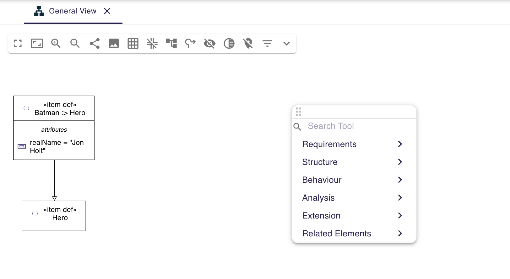
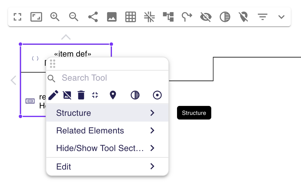
Inside a tool section (for example the Structure tool section):
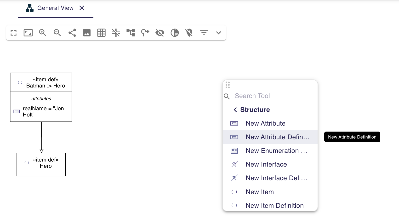
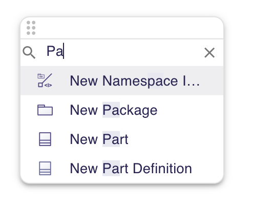
The palette has a search field allowing to search in all tool sections.
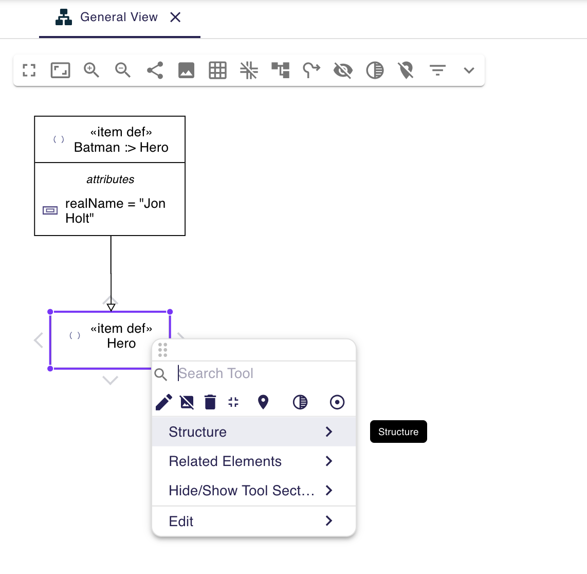
Users can also create elements inside other elements. User just right-clicks on the element to display the palette and then click on the desired creation tool.
All created elements are collapsed by default. This means that when a node with compartments is created, its compartments are hidden.
If a node contains compartments, users can add an element to the desired compartment by right-clicking the compartment to display the palette.
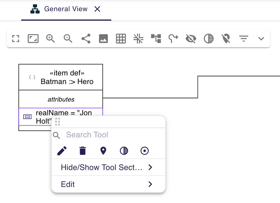
Another way is to right-click the parent node header of the compartment. The palette is displayed, and users can select the desired creation tool from a tool section. The new element is created in the appropriate compartment.
4.2. Delete element
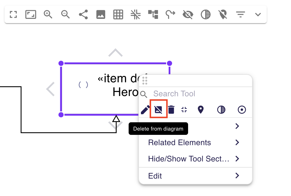
Users can delete a graphical element from the diagram without removing it from the model. Click the Delete from diagram button in the palette.
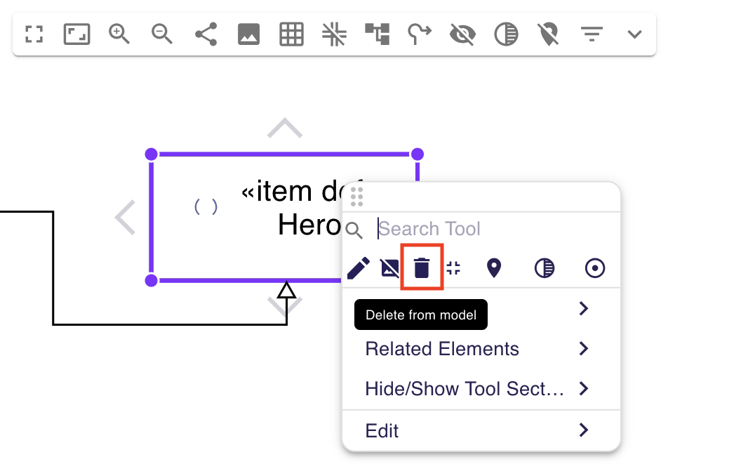
Users can also remove an element from the model (and therefore from the diagram) by clicking the Delete from model button in the palette.
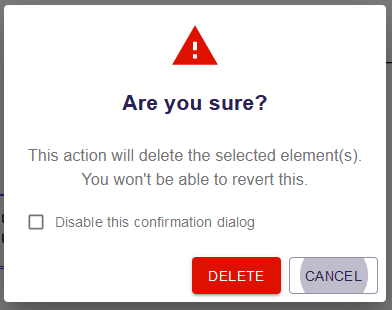
A confirmation dialog appears when an element is deleted via the Delete from model tool in the palette or via the Model Explorer. This behavior can be disabled by checking the "Disable this confirmation dialog" checkbox in the dialog.
|
This preference is stored in the local storage of the browser. You can reset it by deleting the SysON data in cache of your browser. |
4.3. Duplicate Element
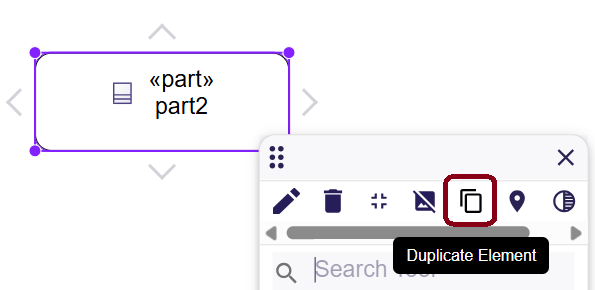
Users can duplicate an Element and its representation node by clicking the Duplicate Element button in the palette.
5. Manage relationships
5.1. Create relationship
Relationship edges can be created between nodes whose types match the edge’s source and target types.
If no edge creation is authorized with a given target, the target node appears faded.
To create an edge, first click the source element to display its arrow border.
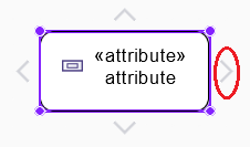
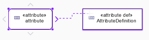
Then click and hold one of these arrows, and drag it to the target. Users can see a preview of the edge, and the target node is highlighted.
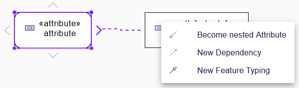
After releasing the click, a pop-up appears and displays all possible kind of edge to create. If only one kind of edge is possible, the edge is created directly without opening the pop-up.
It is not possible for now to create a graphical edge between two graphical edges or between a graphical edge and a graphical node.
| In some cases, if SysON detects that the relationship you try to create already exists and creating a duplicate is not valid, it will tell you with a feedback message instead of creating a redundant relationship. |
For edges representing a structural element such as ConnectionUsage, the created semantic element is owned by the most specific common context of both the source and the target.
5.2. Reconnect relationship
Users can reconnect edges by dragging the source or target end of an edge to a new element.
If the new source or target is not valid for reconnection, it is faded.
For edges representing a structural element such as ConnectionUsage, reconnecting the source or target may move the semantic element to a new owner, following the rule described in the previous chapter.
5.3. Delete relationship
To delete a relationship from the model, click the edge and then the delete button.
Relationship edges are always synchronized. You cannot delete a relationship edge only from a diagram.
Containment relationships cannot be deleted from the diagram. Other relationships can be deleted from the diagram.
6. Manage Labels
6.1. Element Label
Keywords on nodes and edges are displayed on the first line of the label. For example, Definition nodes are prefixed with "part def" and Usage nodes with "part".
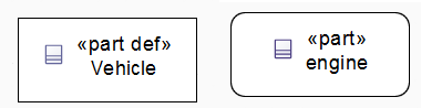
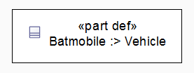
After the keyword, the label can be the simple name of the element or more complex in specific cases. For example, a subset of the SysML v2 textual syntax is supported to describe some elements. For a simple Definition element, the label displays the keyword "part def" and its declared name. For elements using specialization, the label displays the kind of specialization. For example, if a Batmobile is a subclassification of Vehicle, its label displays the keyword "part def" followed by "Batmobile :> Vehicle" to show its specialization of Vehicle.
If a Usage element is defined by a relationship with multiplicity, the multiplicity value (upper and lower bounds) is specified in brackets in the label, just before the specialization. For example, if a Batmobile contains four Wheel elements through the Usage wheels, the label is composed of the keyword "part" followed by wheels[4] : Wheel, which describes the Usage wheels with a multiplicity of four defined by the Definition Wheel.

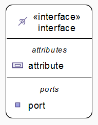
For an element with a compartment node using a list layout, the compartment node label is displayed in italic and contains only a simple name.
6.2. Edge Label
No label is defined on edges except in two cases:
-
An allocation edge label is specified with the allocate keyword.
-
An edge that represents a relationship with multiplicity has its multiplicity defined in its label (for example, a containment edge).
6.3. Edit Labels
Element labels can be edited in the following ways:
-
Edit action of the Palette,
-
Press F2,
-
Type directly the new name.
With direct editing, users cannot change the keyword but can change the name. For a simple label, users can rename the element. If users modify the multiplicity defined in the label, the multiplicity of the relationship changes in the model. Users can also set or change the specialization of a given element.
Explore further by referring to the following how-tos for direct edit action
Labels of edges and compartment nodes cannot be edited.
7. Semantic Drag&Drop
Users can select elements in the Explorer view and drag them into their container nodes in the diagram. This drag and drop doesn’t perform any semantic modification. Diagrams also allow semantic drag and drop of any element from the Explorer view (in the same resourceSet as the diagram) on the background of the diagram.
Note that it’s not possible to Drag and drop an element represented as an Edge on the diagram.
8. Graphical Drag&Drop
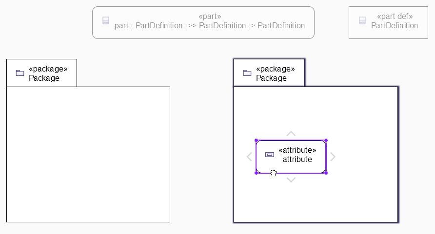
Users can select a node on the diagram and drag it into another container node. Only authorized containers are revealed on the diagram, forbidden targets are faded. When users drag a node, the target container node is highlighted.
9. Manage existing elements
From the diagram background or from a given node, it’s possible to display all existing elements contained by the initial selection.
Open the palette and expand the Related Elements section.
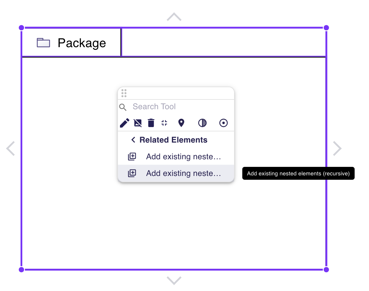
Click Add existing elements to display elements directly contained by the selection. Click Add existing elements (recursive) to display elements directly contained by the selection and their descendants.
9.1. Add existing connected elements
In the General View, select a node, open its palette, and choose Add existing connected elements in the Related Elements section. The tool displays existing project elements connected to the selection through incoming or outgoing relationships supported by the General View. Unlike Add existing elements, it follows connections rather than only containment. It does not create new semantic elements or import elements from standard libraries.
You can also select several nodes and run the tool from their shared palette. The tool considers connections to all selected nodes. It is also available from a node’s compartment, where it uses the enclosing element as the selection.
Connected elements that can be displayed as ports or inside a compartment or container of any selected node are not added as separate nodes. This also applies when the compartment is hidden or has not yet been displayed; the tool does not reveal it. Existing representations are preserved.
For example, when a selected part is connected to another independent part, the tool can display that other part. An attribute or port that can be displayed inside or on the selected part is not added as a separate node.
9.2. Expose Package
When a Package is created in a diagram, it is exposed in the ViewUsage corresponding to the diagram, as any other element created from the diagram.
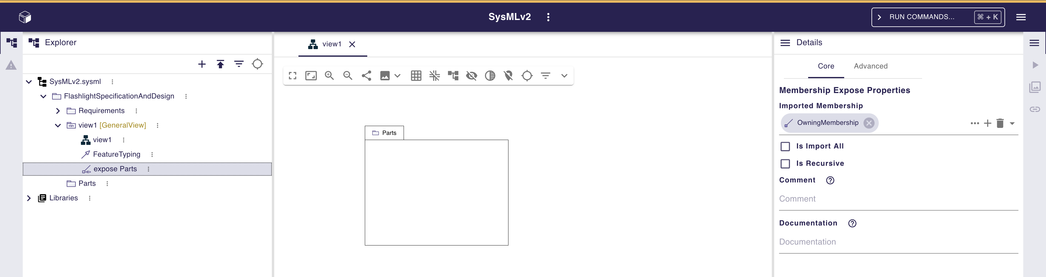
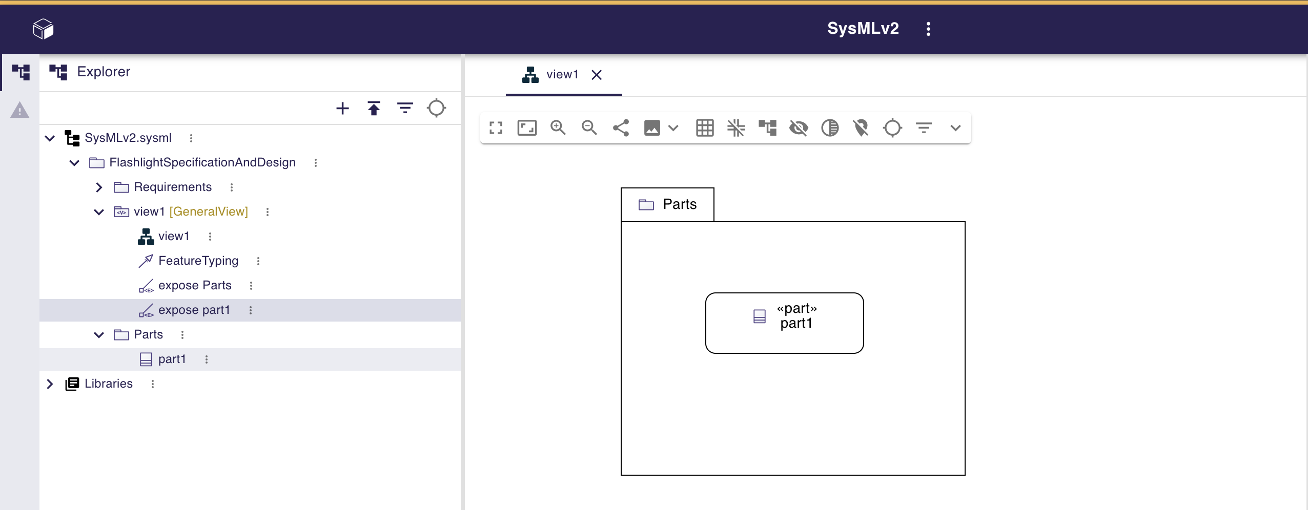
By default, the expose element (a MembershipExpose) corresponding to the Package is not set to recursive. It means that every element created inside the Package will be automatically exposed in the ViewUsage, in its own expose element (a MembershipExpose).
To expose all elements contained by a Package, set the Expose element corresponding to the Package to recursive. In the Details view of the expose element corresponding to the Package, just check the is Recursive property. Then you will see a "::**" at the end of the expose element label in the Explorer view.
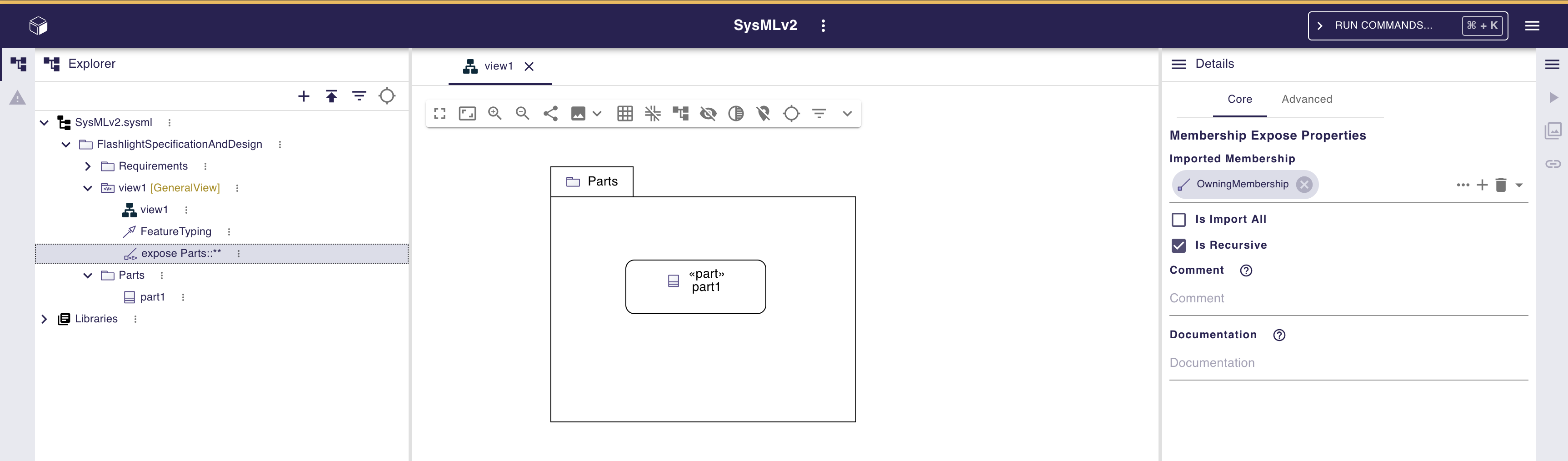
When the is Recursive property is set, all elements contained by the Package are automatically visible inside the Package graphical node in the diagram. No new Expose element is created in the ViewUsage when a new element is created inside the Package graphical node. In this case, this also means that the Delete from Diagram action will have no effect on those elements.
10. Manage multi-elements
When users select multiple elements, several actions are available to manage the selected elements.
10.1. From toolbar
After users select elements, a simplified toolbar is displayed.
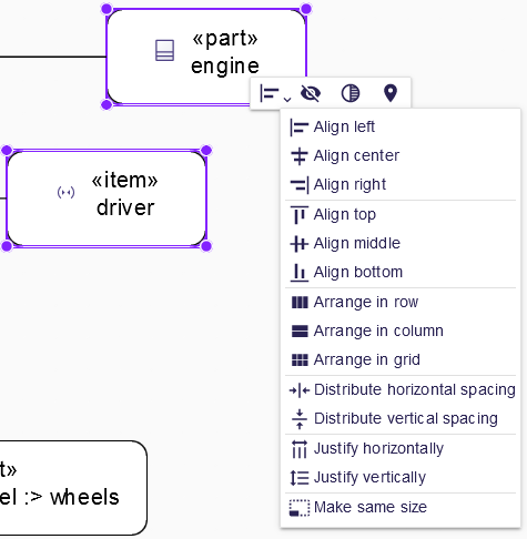
Users can still use basic tools such as:
-
Hide elements,
-
Hide all their content,
-
Show their valued content,
-
Remove elements from the diagram without deleting them from the model with Delete from diagram,
-
Fade elements,
-
Pin elements.
A layout tool section appears in this toolbar. Many tools acting on selected elements layout can be found in this tool section :
-
Align left,
-
Align center,
-
Align right,
-
Align top,
-
Align middle,
-
Align bottom,
-
Arrange in row,
-
Arrange in column,
-
Arrange in grid,
-
Distribute horizontal spacing,
-
Distribute vertical spacing,
-
Justify horizontally,
-
Justify vertically,
-
Make same size.
10.2. From mouse and shortcuts
In addition to toolbar actions, some actions can be execute with shortcuts.
After selecting elements, users can press the Del key to remove them all.
Users can also move all selected elements on the diagram without changing their graphical or semantic parents.