Model Your First System
This tutorial provides a beginner-friendly guide to creating your first system with SysML v2 and SysON, adapted from the training SysML v2 Introductory Training Flashlight Starter Model by Sanford Friedenthal. The focus is on representing a flashlight.
1. Step 1: Create a Project
-
Open the Projects Browser and create a new SysML v2 project by clicking on the SysML v2 card.
-
The Project Editor automatically opens, creating a new project named
SysML v2with a packagePackage1. A defaultGeneral viewrepresentation associated with the package is opened in the main editor area. -
From the project toolbar, rename the project to
Flashlight. -
From the Project Explorer, rename the model to
Flashlight.sysmland the package toFlashlight_StarterModel.
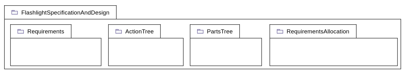
2. Step 2: Model Organization (Package Structure)
-
In the main editor area, right-click on the diagram background to open the palette.
-
Click on
Structure→New Packageto create a new package. -
Rename the package to
FlashlightSpecificationAndDesign. -
Right-click on the
FlashlightSpecificationAndDesignpackage, selectStructure→New Packageto create a new package inside it. -
Rename it to
Requirements. -
Right-click again on the
FlashlightSpecificationAndDesign, and use the quick access toolNew Package. -
Rename it to
ActionTree. -
Repeat the earlier step to create and rename the following packages inside
FlashlightSpecificationAndDesign:-
PartsTree -
RequirementsAllocation
-
-
Click on the
Arrange all elementsmenu in the global toolbar at the top of the diagram.
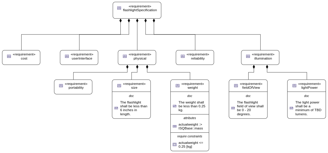
3. Step 3: Flashlight Requirements Tree
-
In the explorer, select the
Requirementspackage, click the "more" menu, and chooseNew representation -
Set the name of the representation to
Requirements General View. -
Create a new
General Viewand open it. -
In the main editor area, right-click on the diagram background to open the palette.
-
Click on
Requirements→New Requirementto create a new requirement. -
Rename it to
flashlightSpecification. -
Right-click on the
flashlightSpecificationrequirement, then selectRequirements→New Requirementto create a nested requirement. -
Rename the new requirement to
userInterface. -
In the explorer, select
flashlightSpecification, click the "more" menu, and chooseNew objects from text. -
In the modal input box, paste the following content:
requirement illumination{
 requirement fieldOfView{
  doc /* The flashlight field of view shall be 0 - 20 degrees.*/
 }
requirement lightPower{
 doc /* The light power shall be a minimum of TBD lumens.*/
 }
}
requirement physical{
 requirement portability;
 requirement size{
  doc /* The flashlight shall be less than 6 inches in length.*/
 }
 requirement weight;
}
requirement reliability;
requirement cost;
-
Select the newly created elements (
illumination,physical,reliability,cost,portability,size,weight,fieldOfView,lightPower) in the explorer (Ctrl + Click), and drag-and-drop them into the diagram. -
Use the
Arrange all elementstool from the diagram toolbar to auto layout the diagram. -
Right-click on the
sizerequirement and selectShow/Hide → Show valued contentto display the documentation in the diagram. -
Repeat the operation for the children of
illumination:fieldOfViewandlightPower. -
Right-click on the
weightrequirement and select theNew Documentationtool. -
In the newly created
docelement, enter the text:The weight shall be less than 0.25 kg. -
Right-click on the
weightrequirement again and chooseStructure → New Attribute. -
Edit the new attribute to
actualweight :> mass. -
Right-click on the background of diagram and use the tool
New Namespace Import. Then selectSI/Library Package SIto import it from the standard libraries. -
Use the palette filter to locate the
New Required Constrainttool, and apply it to theweightrequirement. -
Edit the constraint to:
actualweight<=0.25[kg]
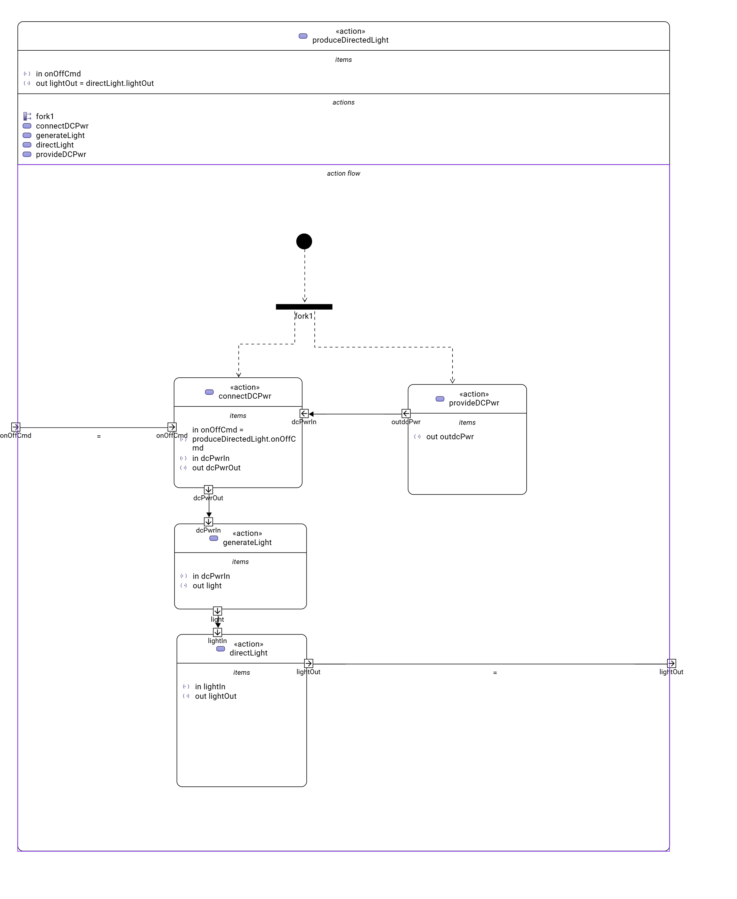
4. Step 4: Produce Directed Light Action Flow
-
In the explorer, select the
ActionTreepackage, click the "more" menu, and chooseNew representation. -
Set the name of the representation to
Action Tree General View. -
Create a new
General Viewand open it. -
In the main editor area, right-click on the diagram background to open the palette.
-
Click on
Behavior→New Actionto create a new action. -
Rename it
produceDirectedLight. -
Right-click on the
produceDirectedLightaction, then selectBehavior→New Start Action. -
Right-click again on
produceDirectedLight, then selectBehavior→New Fork. -
Rename the fork to
fork1. -
Select the start node and use the connection tool to create a succession between the start action and the fork node.
-
Right-click on the
produceDirectedLightand selectBehavior→New Actionto create a nested action. -
Rename the nested action to
provideDCPwr. -
Select
fork1and use the connection tool to create a succession to theprovideDCPwraction. -
Right-click on
provideDCPwr, then selectStructure→New Item Out. -
Rename the item to
outdcPwr. -
In the explorer, select the
produceDirectedLightaction, click the "more" menu, and chooseNew objects from text. -
In the model input box, paste the following content:
in item onOffCmd;
out item lightOut;
action connectDCPwr {
  	in item onOffCmd;
  	in item dcPwrIn;
  	out item dcPwrOut;
}
action generateLight{
  	in item dcPwrIn;
  	out item light;
}
action directLight{
  	in item lightIn;
  	out item lightOut;
}
-
In the
action flowcompartment ofproduceDirectLightuse the toolRelated Elements → Add existing element. -
Create a new transition between
fork1andconnectDCPwr. -
Set the value of
connectDCPwr::onOffCmdby renaming the itemin onOffCmdofconnectDCPwrtoin onOffCmd = produceDirectedLight.onOffCmd -
Create a
Flow Connection (flow)fromdcPwrOutofconnectDCPwrtodcPwrInofgenerateLight. -
Create a
Flow Connection (flow)betweenlightofgenerateLighttolightInofdirectLight. -
Create a
Flow Connection (flow)betweenoutdcPwrofprovideDCPwrtodcPwrInofconnectDCPwr. -
Using the eye icon on the
produceDirectLightaction display theitemscompartement -
Set the value of
produceDirectedLight::lightOutby renaming the itemout lightOutofproduceDirectedLighttoout lightOut = directLight.lightOut.
5. Step 5: Flashlight Interconnection
-
In the explorer, select the
PartsTreepackage, click the "more" menu, and chooseNew representation. -
Set the name of the representation to
Parts Tree General View. -
Create a new
General Viewand open it. -
In the main editor area, right-click on the diagram background to open the palette.
-
Click on
Structure→New Partto create a new part usage. -
Rename it to
flashlight. -
Right-click on
flashlight, then selectStructure→New Attribute. -
Edit it to
mass :> ISQ::mass -
Right-click again on
flashlight, and use the quick access toolNew Attributeto addfov:Real. -
Right-click again on
flashlight, and use the quick access toolNew Attributeto addilluminationLevel:Real. -
Right-click on
flashlight, then select theBehavior→New Performand select the actionproduceDirectedLightcreated earlier. -
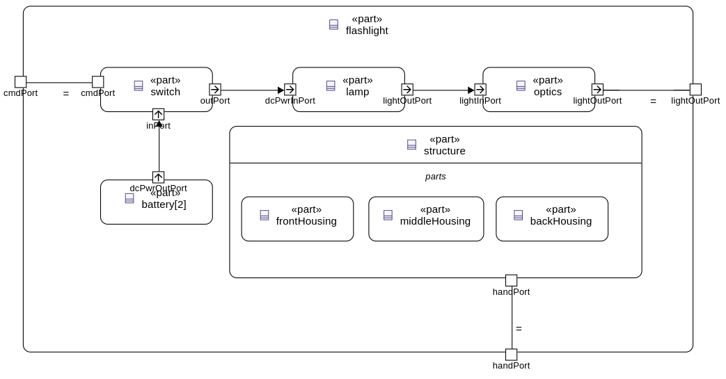
In the explorer, select the
flashlightpart, click the "more" menu, and chooseNew representation. -
Set the name of the representation to
Flashlight Interconnection View. -
Create a new
Interconnection Viewand open it. -
Right-click on
flashlight, then select theStructure→New Port. -
Rename it
cmdPort. -
Right-click on
flashlight, then select theStructure→New Partto create a nested part. -
Rename it
switch. -
Right-click on
switch, then select theStructure→New Port. -
Rename it
cmdPort. -
Create a new binding between the
cmdPortofflashlightand thecmdPortof theswitch. -
Right-click on
switch, then select theStructure→New Port In. -
Rename it
inPort. -
Right-click on
switch, then select theStructure→New Port Out. -
Rename it
outPort. -
Right-click on
flashlight, then select theStructure→New Partto create a nested part. -
Rename it
battery. -
In the
Detailsview, select theAdvancedtab and uncheck theIs Compositeproperty, to declare that this is a reference. -
Edit it to
battery[2]to declare that the part has a multiplicity equal to 2. -
Right-click on
battery, then select theStructure→New Port Out. -
Rename it
dcPwrOutPort. -
Select
dcPwrOutPort, create a flow betweendcPwrOutPortandinPort. -
In the explorer, select the
flashlightpart, click the "more" menu, and chooseNew objects from text. -
In the model input box, paste the following content:
port lightOutPort;
port handPort;
part lamp{
  attribute efficiency:Real;
  in port dcPwrInPort;
  out port lightOutPort;
}
part optics{
  in port lightInPort;
  out port lightOutPort;
  part reflector{
  	attribute radius :> ISQ::length;
  }
  part lens;
}
part structure{
	port handPort;
  part frontHousing;
  part middleHousing;
  part backHousing;
}
-
Drag and drop the newly created parts
lamp,optics,structureinto theflashlightpart. -
Create a new binding between the
lightOutPortofflashlightand thelightOutPortof theoptics. -
Create a new binding between the
handPortofflashlightand thehandPortof thestructure. -
Select
outPort, create a flow betweenoutPortanddcPwrInPort. -
Select
lightOutPort, create a flow betweenlightOutPortandlightInPort.
6. Step 6: Flashlight States
-
In the explorer, select the
flashlightpart, click the "more" menu, and chooseNew representation. -
Set the name of the representation to
Flashlight General View. -
Create a new
General Viewand open it. -
In the main editor area, right-click on the diagram background to open the palette.
-
Click on
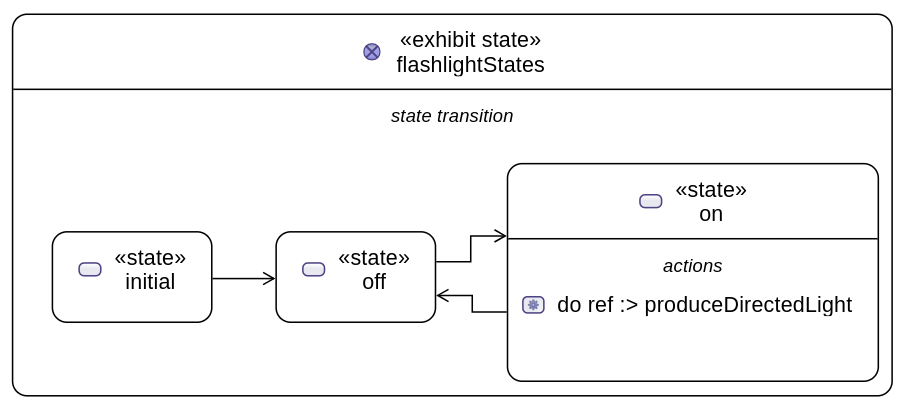
Behavior→New Exhibit Stateto create an exhibit state usage. -
Rename it to
flashlightStates. -
Right-click on
flashlightStates, then select theBehavior→New Stateto create a three nested states. -
Rename them to
initial,off, andon. -
Create transition named
initbetween theinitialstate and theoffstate. -
Create the following transitions between the
onstate and theoffstate.-
transition
off_To_onfromofftoon -
transition
on_To_offfromontooff
-
-
Right-click on the
onstate, select theBehavior→Do Action with referenced action, and select theproduceDirectedLightaction defined earlier .
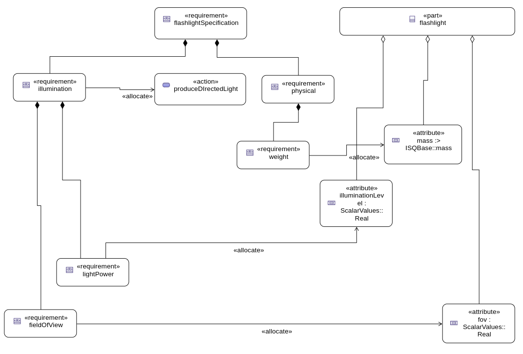
7. Step 7: Flashlight Requirements Allocation
-
In the explorer, select the
RequirementsAllocationpackage, click the "more" menu, and chooseNew representation. -
Create a new
General Viewand open it. -
Drag and drop the following elements from the explorer to the diagram :
-
Requirements:
-
flashlightSpecification, -
illumination, -
fieldofView, -
lightPower, -
physical, -
weight;
-
-
Part:
-
flashlight;
-
-
Attributes of
flashlight:-
mass, -
illuminationLevel, -
fov;
-
-
Action:
-
produceDirectedLight.
-
-
-
Create the following allocations:
-
illumination→produceDirectedLight, -
weight→mass, -
fieldOfView→fov, -
lightPower→illuminationLevel.
-